X_Aton
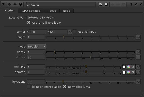
This tool is an advanced variation on the God Rays node. It creates volumetric lighting effects with more realism. It supports soft and diffused light rays created by area lights and volumetric lights. It supports Nuke 3D Cameras, Point Lights and Axis to have a better control of the direction of the illumination.
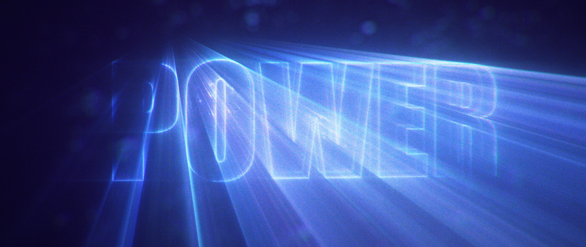
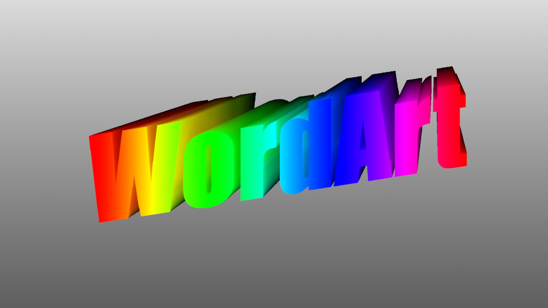
The tool can also be used as a simple screen-space extruder, to create apparent 3D texts or extruded shapes. Now you can do WordArt from the 90s inside of Nuke!
All of this using the power of the GPU to speed up the calculations.
Generates soft focus rays for a more natural and realistic look.
Blinkscript allows the algorithm to run on both GPU and CPU.
Control the quality of the filter to minimize your render times.
Use your custom 3D lights and 3D Camera to drive the effect.
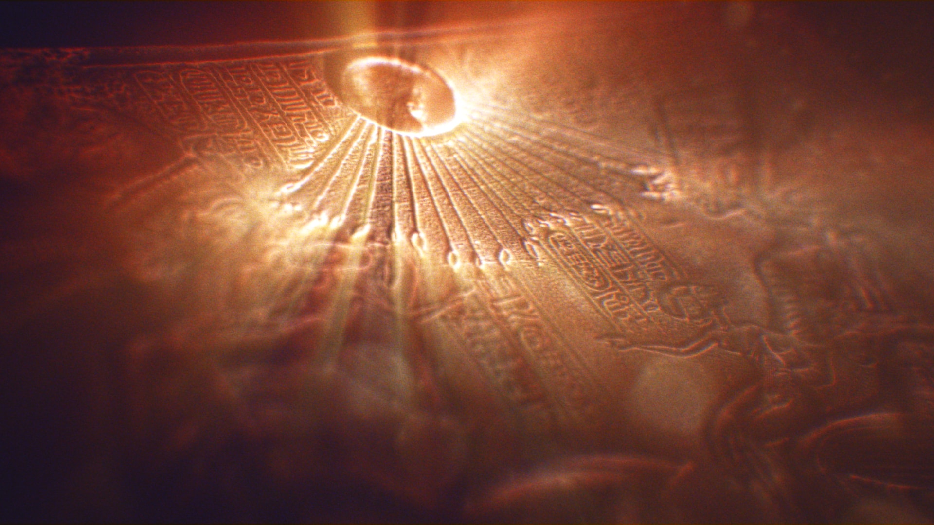
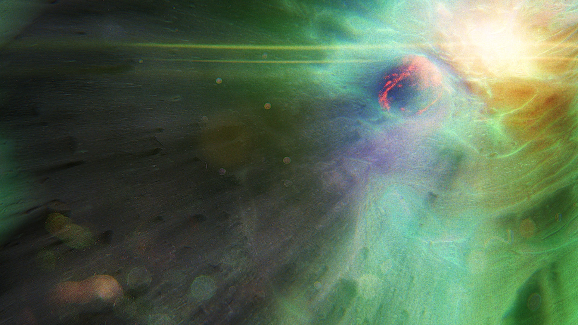
Examples


How does it work?
Looking at Nature
Volumetric Rays, also knows as God Rays, are a common phenomenon in nature. We’ve all seen them in clouds or on the road on a foggy day. The fact that we’ve all seen them and we are used to them means that our eyes have a good memory of how they look like, making it harder to accurately replicate them. Light is such an essential part of nature that we are all, even if unknowingly, very familiarized with its behaviour.
And God said: “Let there be light”, and there was light.
Well, I’d say light happens to be slightly more complicated, but who am I to argue with the Creator. Let’s pretend we have no idea what light is about, let’s forget any preconception and previous knowledge regarding the laws of physics and optics. We are going to look at some examples of different scenarios and try and find what they have in common. Pictures, by the way, are from this website.
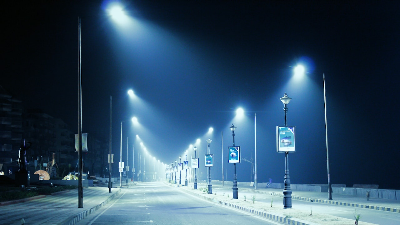
A light source will project a beam of light outwards. This can be seen, for instance, in street lights and lamps.
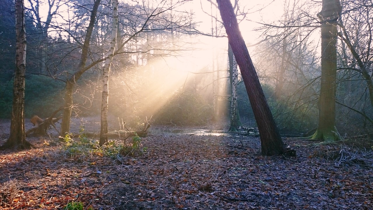
When sunlight gets occluded by leaves or other objects it casts rays towards the camera.

The negative of this effect can be seen in shadow rays when the beam is darker than its surroundings.
Have a moment to look at those pictures. What elements do they have in common? Now, it may not surprise you if I say that these 3 apparently different phenomena can indeed be explained by the same rules. We’ll look at these simple rules one by one and see how they affect the final result. In case it is not obvious enough this is not meant to be a lesson in advanced mathematics. I am not a physicist specialised in optics (although I happen to be the son of one), so take everything from here with a pinch of salt. Warnings said: let’s begin!
Basic Principles of Light
Direction


Light always moves in a straight direction. Also, that is not true at all. You can prove it right at home with some simple experiments. Just look at the refraction of a straw inside a glass full of water or maybe the bending of light as it uses the pull of gravity to orbit the event horizon of a singularity.
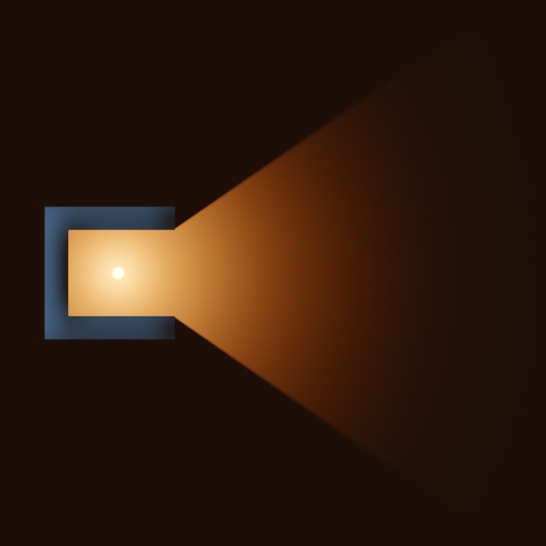
Luckily for us, as long as the light doesn’t change its medium of propagation and we keep a reasonable distance to any nearby black holes, we can assume light moves in a straight line. That means that if we have a point that emits light, rays will travel outwards in a straight direction. That is until they get blocked by any object on its path.
Decay

The further we get from an object, the smaller its size appears to be. In a similar way, lights far away appear to be dimmer. This is why our sun shines brighter in our sky than the rest of stars and galaxies. The intensity (I) at a certain point can be calculated by the brightness of the light (L) divided by the square of the distance (d).

If you live in flatland, know that in a 2D world the distance isn’t squared. In a nutshell, light loses intensity as it travels away from the source. It is a good idea to give artists control of the power of the decay.
Diffusion
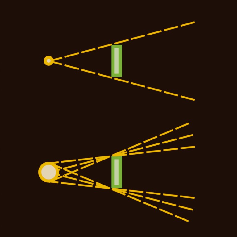

Light beams are not always crisp and sharp. There are two reasons for that. Light scatters through volumes, bouncing randomly and spreading in different directions. The second reason has to do with the shape of the light source.
Most light sources aren’t perfect points, they usually have some volume (i.e, a lightbulb or the sun). This makes rays be out of focus, smoothing out the light beams the further they get from any obstacle.
Having a natural focus (or rather defocus) on the rays is key to creating realistic volumetric effects.


Swipe to compare both images. On the left, a diffused volume with soft decay. On the right, a sharp volume without diffusion.
Scripting a Simple Ray Filter
What is BlinkScript?
We are about dive into the exciting world of Blink Script. This is a scripting language developed by Foundry. It’s very similar to C++, but what makes it really interesting is first, the ability to run both on the GPU and CPU, and secondly the ability to compile it from inside of Nuke, making it very interactive and user-friendly.
This being said, I do not consider it an easy-to-learn language. If you’ve had no contact at all with any programming language, feel free to follow the tutorial, but do not get scared if you find it too complicated. You may want to find some Python tutorials to get familiarised with the basic concepts of programming.
In this tutorial, we are going to create a simple GodRay filter. If you do not have Nuke or your Nuke version doesn’t support Blink, do not despair! You can still learn from this, and you may be able to apply the script to other applications or languages.
You may want to open the Blink documentation in a different tab, in case you get stuck or you want to learn more about a specific term.
Alright then! Everyone on board! LET’S BEGIN!
Let’s start! The shell of the script
Most BlinkScripts start with the word “kernel“. We give this code a name “My_First_GodRay“. We also specify what type of kernel this is. In this case, an “ImageComputationKernel” has the type “eComponentWise“, meaning that it will be applied to each component of the image (red, green, blue and alpha). This is just the “shell” of the actual script, we haven’t really started yet, so don’t overthink it.
Creating the Input and Output
Now we’ll create two images. One to read data from and the other to write data to. In other words, we are creating an input and an output.
The input is called “src“, it’s an “eRead” image meaning that, well, we can read from it. The “eAccessRandom” means that we can request the value of any pixel we want anywhere in the image. The “eEdgeClamped” means that if we sample outside the bounds of the image, that value will be clamped to the nearest pixel in the image.
For the output, we have called it “dst” and we have stated it’s an “eWrite“, an image we can write into.
The process() function
Next, we will define the process function. This is the core of the kernel, the instructions that will be compiled and sent to the GPU/CPU.
Just to start, we will say that the “dst()” image (our output) should equal 1. If we compile this script, the node will return a constant of 1.
Reading the input, writing the Output
Remember we set the “src” image to have an eAccessRandom method? The access random method allows us to get the value of the input in a different position than the pixel we are currently computing. For instance, when we are working on the pixel xy=(20, 100) we could get the value of the input at xy=(10, 50).
Here we have created an int2 parameter in the void process() called “pos“. This parameter will contain the position of the current pixel that is being calculated. Then we can request the value of the input at those coordinates. The result should be… well… that the image goes through the node unchanged.
Creating a scale parameter
Let’s start adding controls for the user. We can define some parameters that will appear as knobs (controls) in the second tab of the BlinkScript node. We’ll start by adding one float parameter called “size“.
We can now divide the position by the size as we are sampling the input and we’ll have a very primitive scaling script. Notice how the resize happens from the bottom left of the image, where the coordinates (0, 0) happen to be. On the next step, we are going to fix that.
Scaling from a center point
Let’s improve the scaling algorithm by adding a “center” parameter. This parameter is going to be a float2, that is a vector with 2 components x and y.
We can sample this parameter using “center.x” and “center.y“. With a little bit of simple maths, we can adjust the scaling to be centered at the point.
A handle should appear in the Nuke viewport to make it more interactive.
Cleaning up the code
Technically there is nothing wrong with the code we wrote in the last step. The line to sample the image tough is getting a little bit long and complicated. You can also spot some repetition. Luckily, there is an easy way to help clean and tidy up the code.
We will create a new variable inside the process() function. This will not show up to the user as a control. We will use this float2 variable called “raypos” to store the position we want to sample the image from. This will help keep the code more clear as we move along adding more stuff in it.
Introducing repeating tasks (loops)
Let’s backtrack for a moment and look at a simple example of how loops work. Sometimes we need to repeat an operation a few times. Instead of copypasting the lines of code, we can put them inside a loop.
This loop works with a counter “i“. This is an integer that we set at 0. When we run the loop, the counter increments by 1 every time. The loop continues while we meet a condition, in this case, that the “i” counter is greater than the parameter called “iterations“. Inside the loop, we have the previously defined float variable “total” and we add 1 on every iteration. The result should be a constant with a value equal to the number of iterations.
Joining the previous steps: sampling inside a loop
Let’s put together everything we’ve learnt so far. We’ll take the scaling algorithm and put it inside the for loop. Our goal is to scale up the image a little bit on every iteration and then average all the iterations together.
See how we are adding the “src” to the “total” variable inside the loop. After that, we divide the total by the number of iterations, to obtain the mean.

When we run the script we see that the scaling still works but the iterations seem to have no effect. This is because we are doing the average of the same image over and over. In the next (and final) step, we are going to sort that out.
Changing the scale based on the iteration
Alright! Let’s finish this! So far the results have been quite unexciting, but I’m sure this is going to change!
We are going to create a new float variable called “raysize“. This is going to store the scaling factor at each iteration, this way we’ll be able to have a different size on each iteration. We will set the expression to be (1+size*i/iterations). Remember that the “i” variable corresponds to the counter in the for loop. It starts at 0 and increments until the number of iterations minus one. Therefore the i/iterations will increment from 0 to 1. In other words, on the first iteration no scaling will be applied and on the last iteration, full scaling will be applied.
If everything is in the right place, you should have a working GodRay node.
Here’s a treat for you. You deserve it. :)
Take a deep breath. Read your code again, line by line. BlinkScript can sometimes be a tricky language. Try and understand what each line is doing.
Are you having some problem? You are not seeing what you expected to see? Maybe some issue compiling it? Try and debug it: where do you think the error comes from? Simplify the code, try to isolate the problem. Try a simpler example, then slowly add stuff back until you find the mistake.
Now play around with the code! See what you can come up with! Here are some ideas:
- Light decay. Make the intensity of each iteration decrease.
- Colourizing. Use can use a float3 parameter to control rgb colour.
- Diffusion. How would you blur an image?
- Translation. Add a translation parameter to control direction.
- Rotation. Not sure what you want this but… sure, go on!

“There are two ways of spreading light: to be the candle or the mirror that reflects it.”
Edith Warton