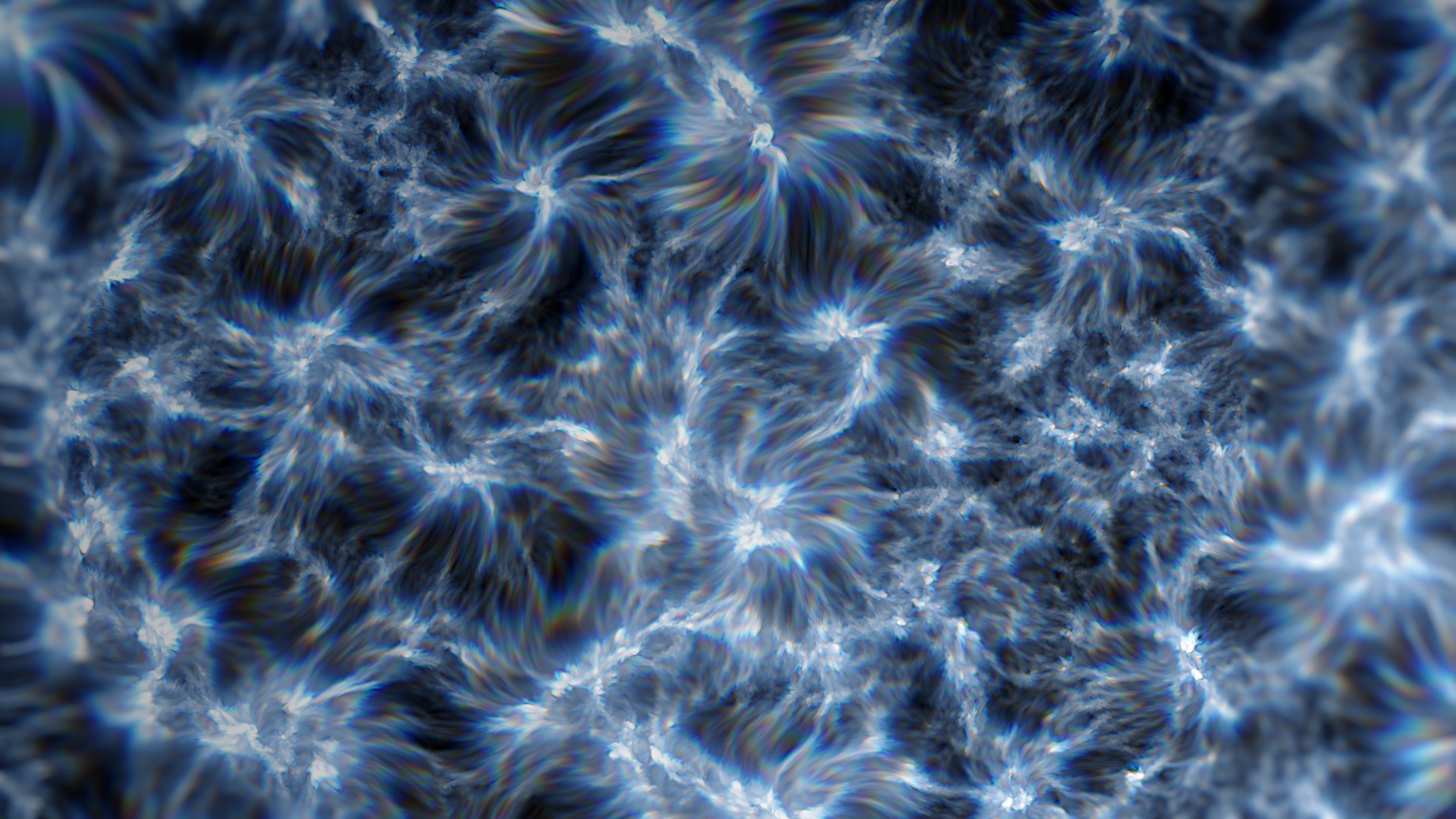
X_Distort gizmo
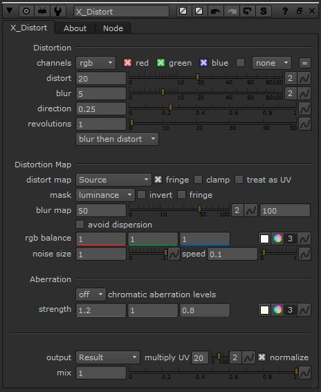
This gizmo I have created allows you to distort footage with control and flexibility. The main difference between my gizmo and Nuke’s IDistort is that is more customizable and that it automatically generates the UV channels needed to distort the image. You don’t need to copy any channels and you have many other useful settings to play with. Another useful feature is that you can blur the parts of the image which are being distorted to get a smoother result.
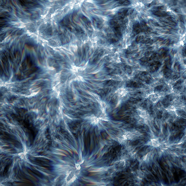
You can distort an image using its own information, distort it using another video as a displacement map or distort using an automatically animated fractal noise. You can choose how much detail the distortion is going to have.
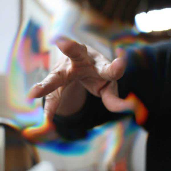
You can also distort each colour per separate, creating a realistic chromatic aberration effect. You can decide the quality of the effect in order to speed up render times.
The gizmo will output the distortion image by default, but you can also export the distortion vectors or a normalized UV normal map to use somewhere else in the composition.
Advanced image-aware deformation.

Natural and stylized looks for your effect.
Take control of every aspect of the distortion.
Even if using extreme distortion settings.
What can I do with it?
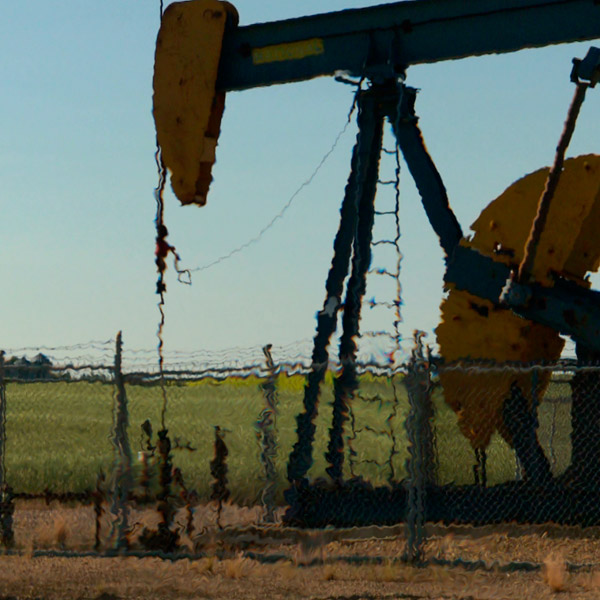
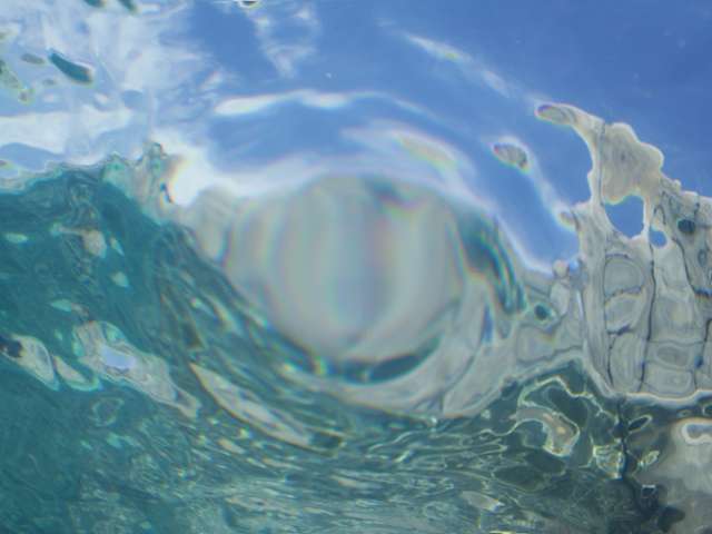
Heat distortion and similar effects
Improving your rotos’ quality
Creating awesome warping effects
Textures and stylized looks
Some cool techniques
Every After Effects user has used at least once the turbulent displace effect. This simple and useful tool for creating basic distortion effects is perhaps one of the most used distortion effects. Perhaps you have also used the displacement map, the liquify, or the CC glass effects. But if you are a Nuke user, you will already know that the only distortion effect you have is IDistort. If you have played with it you will know that it is not very “user-friendly”, as you need a UV map input in order to distort. Well, guess what? You can create all of those effects and more with this gizmo. These are just a couple of examples of what can be achieved using different techniques with my gizmo. Of course, you can push the limits as far as you want.
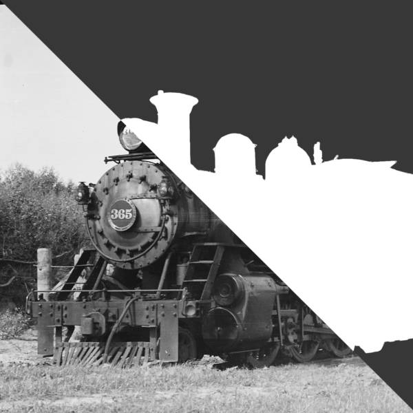
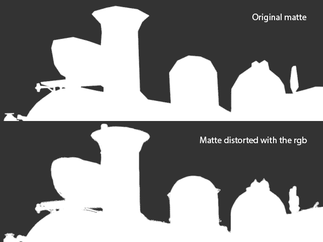
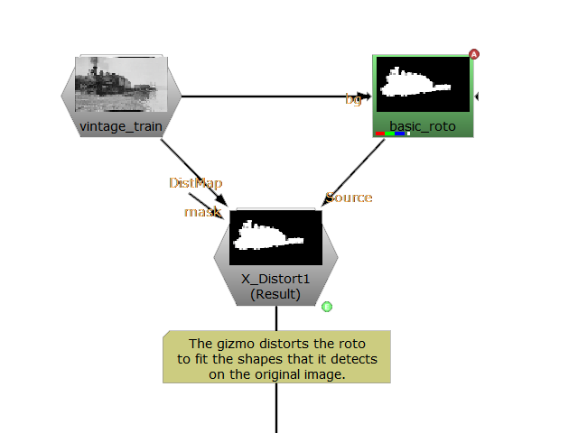
Refine Edge Matte
This is, perhaps, one of the greatest potentials of this gizmo. Using the correct settings you can adapt a roto to fit the shape on the original image. The way to achieve this is by using the matte as the source to distort and the original clip as the distortion map.
Twirl / Bulge effect
To make a twirl effect we use a radial gradient and select it as the distortion map. If we set the direction to 0.25, the image will be distorted in a spiral way. We can reverse the direction of the spiral if we use a negative distortion or if we set the direction to 0.75. If we set the direction to 0 or 0.5 instead the radial will puck or bloat the original image, creating a bulge effect. We can use the distortion map blur to make the edges of the effect smoother. We could also multiply the radial gradient with some noise to get a more chaotic result.
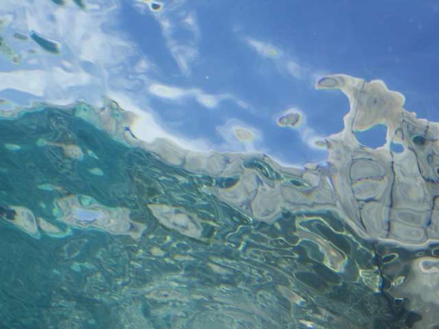
The original image
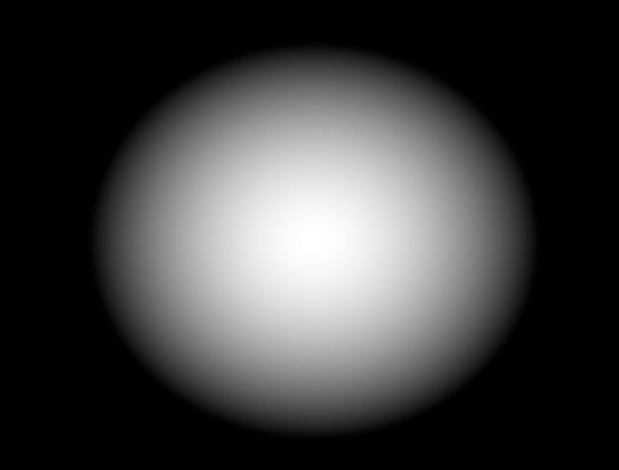
The radial ramp
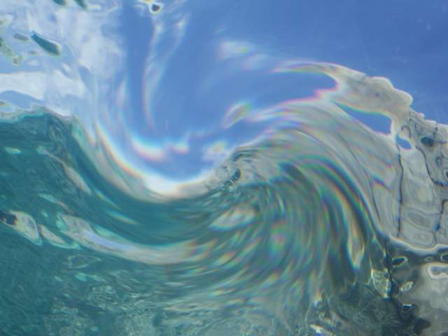
Twirl, direction set to 0.25
Bulge, direction set to 0.5
Pixelated Distortion
It is recommended that you always keep the distortion quality at 100. It won’t make any difference over 100. Low-quality distortion can also be useful as an abstract effect though. First, set the blur quality under 5 (or even 0 and -1!). Next, blur the distortion map over 100. This will make the distortion look “blocky” by removing all detail. Another way to achieve this is to use a checkerboard as a mask. This will make that the only area that is distorted is the one in white squares.
Developer‘s guide to distortion
The next bit is going to be a little bit technical. I will be talking about how distortion works, from the basics of what distortion is to some advanced techniques to get some cool stylized looks. When using an artistic tool, it is important to understand how it works. Perhaps some of the maths below can be a little bit tricky, but the idea behind distortion is much simple than what you might think. I will try to explain as simple as I can. Warning: I will be oversimplifying everywhere!
What is distortion?
Distortion consists of moving pixels in a nnon-uniformway. That’s it. But simple does not mean easy. We need a way to tell the program which pixels are going to be translated, how far will they move and in which direction. Every pixel will have a different intensity and direction. So our distortion vector (v) has a magnitude (m), and a direction (θ).
![]()
This can also be expressed in a vectorial notation. That means we have a magnitude for x and a magnitude for y, so we don’t need the angle (it is already implicit in this new form). Because calling them x and y would be unoriginal and confusing, let’s call them U and V. The U value indicates how much horizontal distortion the pixel has. The V vector indicates the vertical distortion.
![]()
How can we distort an image?
Now we understand the basics of distortion. But how we define the U and V values for each pixel? The only information we have is the RGB channels. An easy way to define the vector’s trajectory for now will be that all vectors will point to the brightest area near them. We could do that by generating a radial field of vectors (a(mn)) which point away from the centre and multiply them for the brightness (l). Then we add all the vectors them together and we have our result.
But having such a big matrix is a very slow process to render. We need an easier solution which is fast and reliable. We could simplify this process by blurring the image using a simple kernel. Then we would only need to use this simple edge detection in the U and V axis. Note how values can be both positive or negative.
![]()
Now that we have our map we have to store it somehow. Normal maps use the red and green channels for encoding the U and V values and the blue channel is often left unused. Now we have to distort the image using our distortion map. This is what IDistort does in Nuke or the Displacement Map does in After Effects.
![]()
And to make this more customizable, we can add a control or knob called “Intensity” (I) that will multiply the distortion map. We can have both an horizontal and a vertical Intensity. or let them be the same A lower Intensity will result in a less distorted image than a high Intensity. So we can redefine the last part of the previous function as:
![]()
Playing with the vectors
But we could have played more with the vectors on the distortion map before distorting the image. A cool effect is to try and rotate all the vectors to a certain direction. We create a user control called “Direction” (D) which will affect the vectors. This can be achieved by the simple trigonometric function (tau used instead of pi):
![]()
![]()
![]()

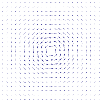
With this formula, we can switch from a radial field to a spiral field. If we set the direction to 0 or 1, the field remains untouched. At 0.25, it becomes a spiral field instead of a linear field (see the images below). At 0.5 we invert the original vector’s direction. At 0.75 we have another spiral field but this time it spins counter clockwise. As you can see we can have many different looks with a single controller:
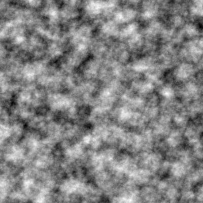
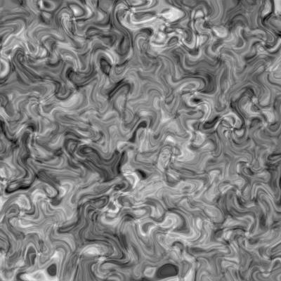
The original noise effect.
Direction set to 0. Radial field. Bright pixels attract dark pixels.
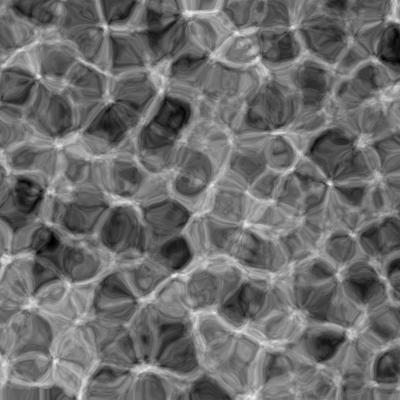
Direction set to 0.25. Spiral field. Dark pixels spin around bright pixels.
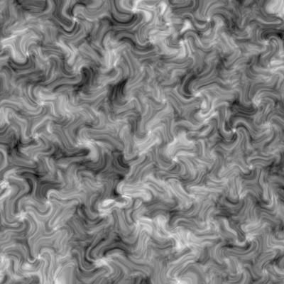
Direction set to 0.5. Inverted distortion. Dark pixels attract bright pixels.
Understanding fringe
Have you ever wondered what that | ☑ fringe | checkbox in Nuke is? The help tip talks about a mathematical formula, but what does that formula exactly do? When using a mask, the effect is applied at maximum when the mask value is 1 and it is not applied when the mask value is 0. But if we apply the formula f(x) = 4(1-x)*x we see that when the mask value is 1, f(1) = 4(1-1)*1. So if the result is 0, the effect will not be applied neither when the mask value is 0, or the mask value is 1. Instead, the mask will only be applied when the values are around 0.5, or a half.
![]()
Standard formula: f(x) = x
Fringe formula: f(x) = 4*(1-x)*x
But there is one problem. This formula only “fringes” positive values between 0 and 1. But the distortion map takes both positive and negative values. We need a formula which does the same thing to values between -1 and 0 and between 0 and 1. Then, this new formula will have its roots on -1, 0 and 1. It will also have a relative maximum of 1 and a relative minimum of -1. We will ignore if the maximum and minimum are at the mid 0.5 grey point. So our new adapted fringe formula looks like this:
Fringe formula: f(x) = 4*(1-x)*x
Adapted fringe formula:
f(x) = ( [3*3^{1/2}]/2)*(1-x^2)*x
As you can see, the difference is clear once you compare both graphs. But how does this affect the final output? If we had a faded mask, the effect would only apply to the edges of the shape. But, we are dealing with a distortion map. What we will see is how dark and bright values are attracted by the middle grey values. Visually, it results in a more liquid look for the distortion. Of course, we can create a checkbox that will switch between both modes. That will add further flexibility to the artist.
Without the fringe formula
With the fringe formula
With the inverted fringe formula.
With the fringe formula + spiral field
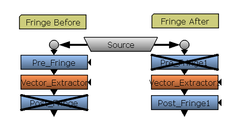
Another dilemma is when should we fringe the image. The are two main possibilities. Possibility number 1: fringe the vectors after they have been extracted and rotated. This option makes a smooth and homogeneous between all the direction phases, but can cause dispersion and some extreme results on highly detailed distortion maps. Possibility number 2: fringe the source image or the distortion map source right at the beginning. Then, the fringe won’t be necessary continuous on every direction angle, but its results will be under control. For my gizmo I chose the second option because it is more reliable and stable.
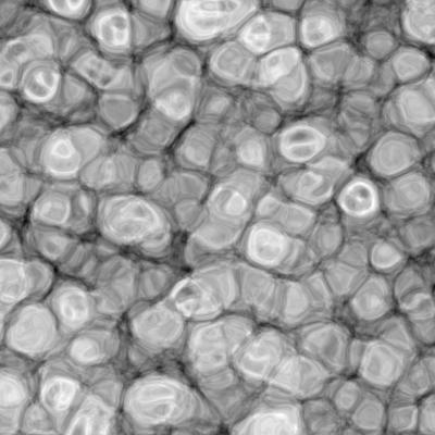
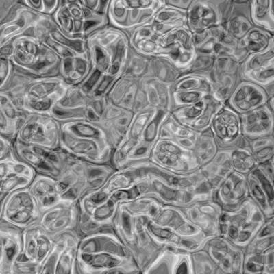
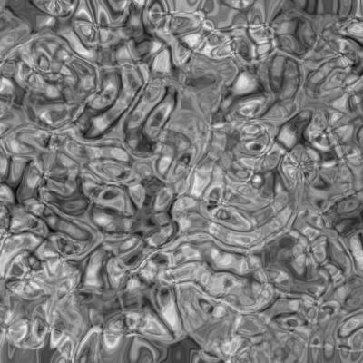
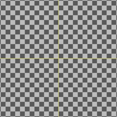
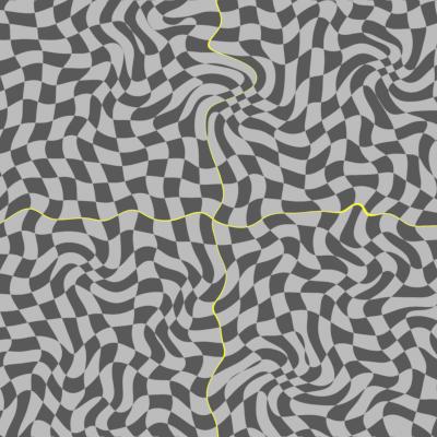
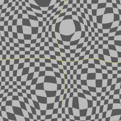
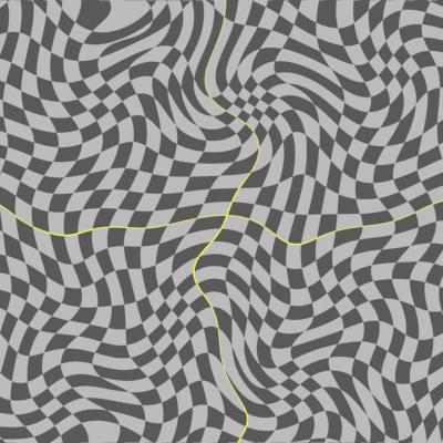
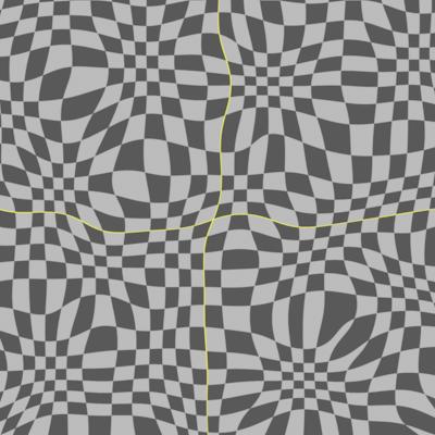
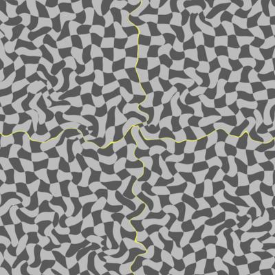
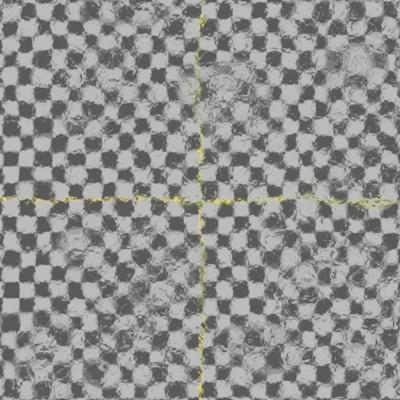
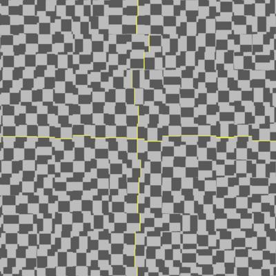
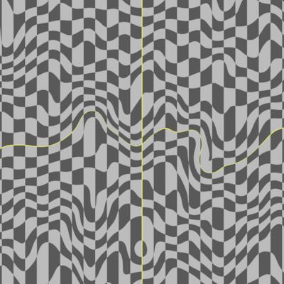
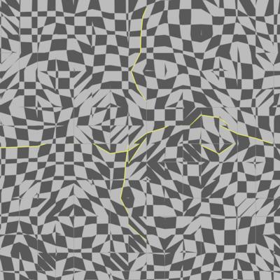
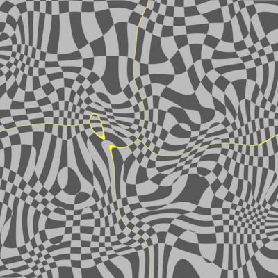
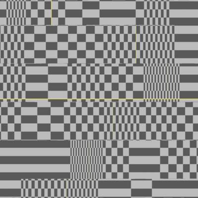
Checkerboard playground
An important part of the development is testing how the tool works on a normalized environment. A checkerboard is ideal for testing if the distortion causes any artifacts or glitches. It’s also important to check all algorithms to the limit, using very big values, to see if they crash the application. It is also important to avoid problems such as dividing by 0, which always happen somewhere. The artist must never get unexpected results. Here there are some tests I did, trying to find different looks using only distortion (my gizmo also supports blur).
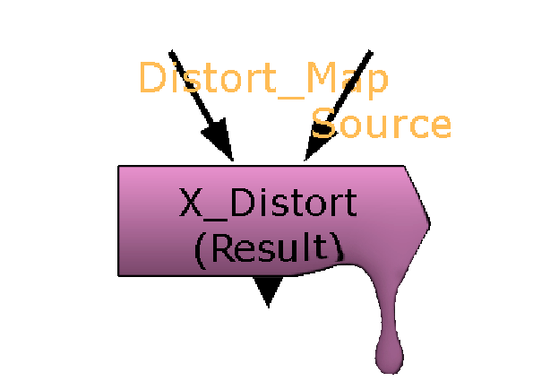
To sum up
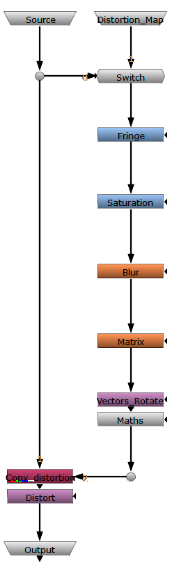
This scheme summarizes how the gizmo works. I have oversimplified the node tree. Actually, it is 10 times larger than this scheme, but this can give you some clues about how it works.
First of all, we input our source. A switch lets us define whether we want the source as the distortion map or not. If we set the switch to 0, the source will be distorted using its own rgb information. If we set the value to 1, the distortion will be applied from the other input.
Secondly, we will decide whether or not we want to fringe the image. This will affect drastically the final output, even if we apply the expression at the beginning of the node chain.
The next step is to average all the rgb values, creating a black and white image. The user can decide the influence of each colour, and how much will they affect the distortion. We could, for instance, distort every colour except red, or use one colour as negative distortion.
Before extracting the vectors, it is necessary that we blur what will become the distortion map. This will speed up drastically the extraction process. The way blur affects the output is by smoothing the distortion and making it global rather than local.
Now it is time to make some mathemagics. The first thing we will do to extract the vectors will be using a kernel (a 3×3 matrix). We don’t need a bigger matrix thanks to the blur we previously added. The kernel will extract the very first vectors to play with.
Two more maths expressions will give us the possibility of rotating and scaling vectors, as well as applying fringe to the distortion map, adding revolutions, etc. This is where we will customize the distortion and decide how it is going to look.
At this point, we copy the distortion map into a new channel. The distortion node will distort the rgb values using the data stored on the distortion map channel. Now we can decide the strength of the distortion and which channels are going to be sent to the output.
The output should be clean, meaning that all the technical channels that are created and used during the effect should be removed before the output.
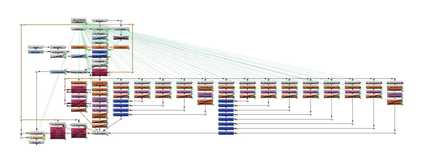
X_Distort node graph as of version 1.5
“One often has to distort a thing to catch its true spirit.”
Robert J. Flaherty